Modification of spontaneous emission
In many applied modeling problems, the question arises about the modification of spontaneous radiation near a nano- or micro-object or inside a nanostructured sample. For example, it may be the process of luminescence or fluorescence of a molecule or supramolecular complex in an organic environment.
In particular, the light emitted by an organic light-emitting diode (1) arises as a result of spontaneous emission during exciton recombination occurring in the emitting layer of the OLED. Recombination is, in fact, the relaxation of an electron from the highest level in the molecular spectrum to the lowest. In this case, the radiative recombination is determined by the dipole moment of the transition between the higher and lower levels. The rate of recombination of excitation (such as exciton) is determined by both the chemical and dielectric environment of excitation, and is the sum of two processes, namely, radiative and non-radiative relaxation. The dielectric environment affects the rate of radiative recombination, which is determined by the local density of photonic states (modes) available to the emitter, as well as non-radiative recombination, or more precisely, the absorption of radiation in the material (so-called ohmic losses). The last process is the famous metallic quenching of spontaneous radiation, which plays a primary role in the study of spontaneous radiation in materials. The chemical environment of the emitter also influences nonradiative recombination. Modeling of the influence of the chemical environment takes place at the atomic level. Below we will not take into account the influence of the chemical environment, because this will not affect the conclusions for radiative recombination and ohmic losses. (2)
The principle of conformity
The correspondence principle plays a key role in the classical electrodynamic approach to calculating recombination rates. According to this principle, the power of spontaneous emission of the excited state of the emitter during a dipole transition corresponds to the power of a classical electric dipole with a dipole moment value equal to the matrix element of the dipole moment of the transition. The rate of recombination is determined by the following expression:
\( \gamma =\frac{P}{\hbar \omega } \),
where \({P}\) is the power, \({\omega}\) is the frequency of radiation. The same is true for a magnetic dipole junction. It is assumed here that both the frequency and the matrix element of the dipole transition practically do not depend on the environment of the emitter, which is true in most cases. The rate of radiative recombination can be obtained by integrating the far field of the emitter over its surrounding surface. The rate of nonradiative recombination is obtained by integrating the energy of the radiation field over the volume of all absorbing objects.
The rate of radiation recombination of a dipole emitter in a given medium is proportional to the power emitted by a classical dipole source located in the same medium (3). Below are examples of such an approach to calculating the decay rates of radiation for a number of cases. -Modeling of Eu3+ complexes located near a metal surface (4) (5) (6). The matching principle used makes it possible to separate the rates of radiation and nonradiative recombination, as well as the quantum yield.
- A dipole near or inside a dielectric sphere (7), (8).
- A dipole near or inside a multilayer sphere (9).
Dipole at the surface
For the first time, the correspondence principle was applied in the simulation of spontaneous emission of Eu3+ complexes placed near a metal surface. Unlike previous works on this topic, where a mechanical model was used, the method described in these studies makes it possible to clearly separate radiative and non-radiative recombination. Thus, information can be obtained both about the rates of both processes, as well as the observed quantum output of the emitter in a complex environment. The observed quantum yield is the ratio of the number of real photons associated with the radiation field of the dipole to the number of excited states created; this value differs from the quantum yield of the dipole in vacuum, which is determined by the ratio of the number of emitted photons to the number of excited states created. When the dipole is near a metal surface, only part of the photons will be emitted into the far zone, while the other part will be absorbed by the surface. The dependence of the luminescence intensity modification on the distance between the emitter and the metal was studied. In addition, calculations were carried out for an emitter located near an absorbing sample of finite thickness, as well as between two partially reflecting mirrors. The given examples of calculations give a visual representation of the model, because they allow an accurate analytical solution.
The method accurately predicts the properties of luminescent molecules near absorbing surfaces. In particular, it allows describing nonradiative recombination at very small distances from the absorbing surface.
Dipole near or inside the sphere
Understanding the properties of spontaneous radiation of emitters near curved surfaces is extremely important both in the development of OLEDs and in the field of luminescent chemo- and biosensors. A complete classical description of the radiation of a dipole located near or inside a dielectric or conducting sphere was proposed in the pioneering works of Chu and Rappin. The sphere problem has some interesting nuances that are absent in the case of plane geometry, such as the resonant interaction of a dipole with a particle at frequencies close to the resonant frequencies of the particle. The method itself is very similar to the Mie formalism for scattering a plane wave on a sphere. The incident (dipole field) and scattered fields are laid out in a row according to vector spherical harmonics, and the corresponding boundary conditions are applied on the surface of the sphere. The coefficients of decomposition are the famous coefficients of Mi. The resulting fields are integrated in the far (wave) zone along the surface of the sphere \({S_{\infty}}\), enclosing both the dipole and the sphere.
\( P^{rad}=\frac{c}{8\pi }Re(\int\limits_{{{S}_{\infty }}}{\left( \mathbf{E}\times {{\mathbf{H}}^{*}} \right)\mathbf{n}dS}) \)
The result of the calculations gives information about the rate of radiative recombination of a dipole source near or inside the sphere.
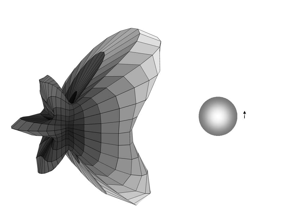
As an example of modification and angular redistribution of dipole radiation in a complex dielectric environment, we study the radiation spectrum and angular distribution of a dipole emitting near a metal sphere. Let the sphere consist of silver and have a radius \( R=80 \) nm, the dipole is removed from the surface of the sphere by \(d=20\) nm and oriented parallel to the surface. A strong maximum appears in the spectrum at the frequency corresponding to the excitation of the local plasmon resonance \(\omega =\frac{{{\omega}_{p}}}{\sqrt{3}}\) (Fig. Figure 1). The angular distribution of radiation at frequencies less than resonant has a very interesting shape consisting of five humps (Fig. Figure 2).
A dipole inside a log-pile type photonic crystal
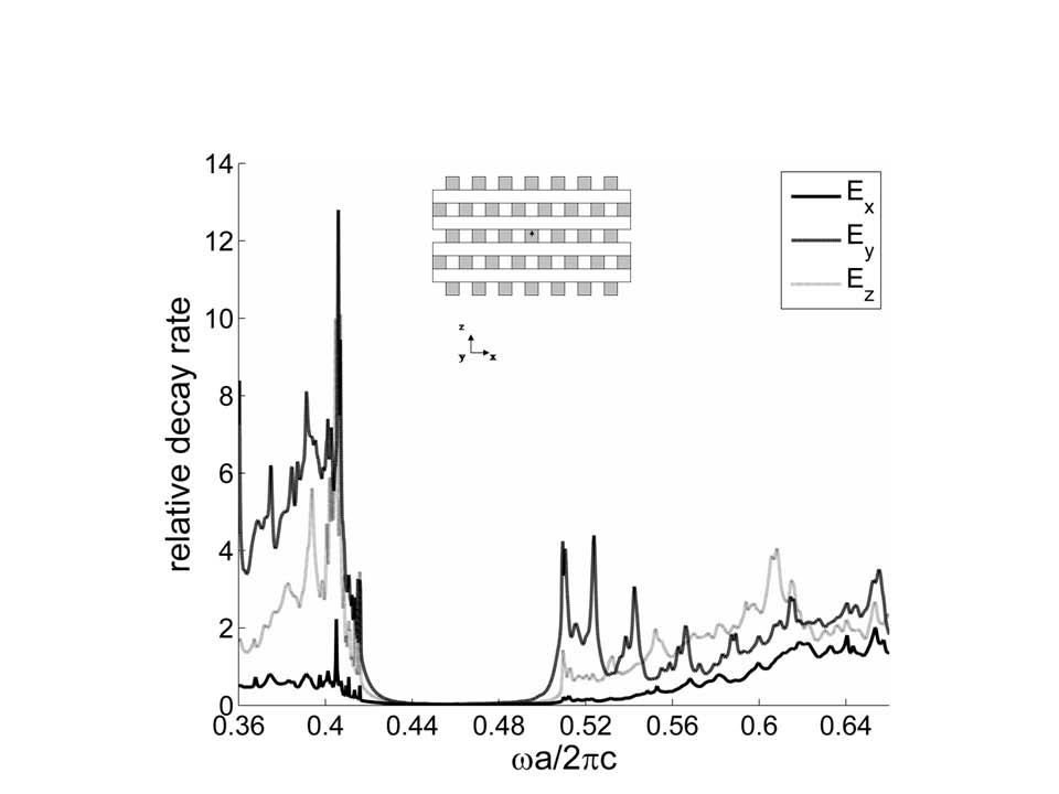
A photonic crystal with a photonic band gap (Photonic band gap, PBG, Eng. ) completely suppresses the radiation of the source located inside the FC. We will show this by the example of calculating the radiation spectrum of a dipole placed inside a log-pile FC. FC consists of dielectric rods arranged in a lattice: in each layer the rods are parallel to each other and the distance between the centers of the nearest neighbors is \( a\). The rods have a rectangular cross section with a thickness of \(w\) and a height of \(h\). The rods are stacked in layers along the z axis. In each subsequent layer, the rods are oriented perpendicular to the rods in the previous layer. The rods through the layer are shifted relative to each other by \(a/2\). Thus, in the z direction, the period is 4 layers. The whole structure has a face-centered tetragonal symmetry. We will consider FC with the following parameters: \(w/a\)= \(h/a\)=0.25 . The material of the rods is GaAs, whose refractive index \(n=3.5\). Such a FC has a wide band gap in the frequency range \(a/ \lambda = 0.43\div 0.50\).
Green's function method
This method is based on the identification of a local communication network (LDO) using the classical Gris dyad (10). The attenuation rate of the emitter depends on its frequency, position, and orientation. Thus, orientation control is crucial for manipulating spontaneous radiation. It turns out that there is no need to measure the attenuation rate for a large set of emitter orientations in order to adequately describe the orientation dependence of the velocity. In (11) describe a method that makes it possible to control the rotation speed by remote control (that is, the rotation speed is attenuation in consciousness from the orientation of the emitter) for a given exposure to the emitter, increasing the speed on the basis of frequency when detecting a possible distribution (below 10). In a special way, using the symmetry properties of the Green function in a given medium, it is possible to derive three main axes for a given position of the emitter and frequency and calculate the corresponding basic coefficients. This approach provides a clear physical picture of the dependences of the radiation velocity in an arbitrary nanostructured medium. The authors also show how controlling the orientation of the emitter opens up new possibilities for switching radiation from suppressed to amplified and vice versa.
Knowledge of the basic velocities and axes is the key to the correct interpretation of the dynamics of orientation dipole ensembles (12), (13), (14), (15).
The decay of such ensembles is the sum of unit exponentials with a velocity distribution given by the radiation velocity surface. Consequently, any observable value obtained from the time-resolved decay over the orientation-averaged velocity requires knowledge of the basic velocities, which, therefore, is relevant to many physical situations in nanophotonics.
- (1) Surface enhanced fluorescence, E. Fort, S. Grésillon, J. Phys. A: The application. Physics. – 2008. – Vol. 41. – p. 013001
- (2) Optical radiation in periodic dielectrics, R. Sprick, B. A. van Tiggelen and A. Lagendijk, Europhys. Latin. - 1996. – Vol. 35. – pp. 265-270.
- (3) Recursive solution of the transfer matrix for a dipole radiating inside and outside a stratified sphere, Annals of Physics – 2005. – V. 315. – pp. 352-418
- (4) Lifetime of a radiating molecule near a partially reflecting surface, R. R. Chance, A. Prok and R. Silby, J. Chemistry. Physics. – 1974. – Vol. 60. – pp. 2744-2748
- (5) Comments on the classical theory of energy transfer by R. R. Chance, A. Prok and R. Silby, J. Physics. - 1975. – Vol. 62. – pp. 2245-2253
- (6) Decay of a radiating dipole between two parallel mirrors, R. R. Chance, A. Prok and R. Silby, J. Physics. - 1975. – Vol. 62. – pp. 771-772
- (7) Atomic transition rates near spherical surfaces, J. Chemistry. Physics. – 1987. – Vol. 87. – pp. 1355-1360
- (8) Radiation and lifetime of atoms inside dielectric particles. Phys. Rev. A. – 1988. – Vol. 38. – pp. 3410-3416
- (9) Recursive solution of the transfer matrix for a dipole radiating inside and outside a stratified sphere, Annals of Physics. - 2005. – Vol. 315. – pp. 352-418.
- (10) Green's dyadic functions in Electromagnetic theory, 2nd ed., New York: IEEE. – 2003
- (11) Orientation-dependent spontaneous emission rates of a two-level quantum emitter in any nanophotonic medium, V. L. Vos, A. F. Kenderink and I. S. Nikolaev, Phys. Rev. A. – 2009. – V. 80. – P. 053802-1-053802-7.
- (12) Enhanced spontaneous radiation by quantum boxes in a monolithic optical microresonator, J.-M.Gerard, B.Sermage, B.Gayral, B.Legrand, E.Costard and V.Thierry-Mieg, Phys. Rev. Lett. – 1998. – V. 81. – pp. 1110-1113
- (13) Control of the dynamics of spontaneous emission of quantum dots by photonic crystals, P.Lodal, A. F.van Driel, I. S.Nikolaev, A.Irman, K.Overgaag, D.Vanmaekelberg and V. L. Vos, Nature. – 2004. – Vol. 430. – pp. 654-657
- (14) Significant increase in the decay rate of radiation emitters using single plasmon nanoantennas, O. L.Maskens, V.Giannini, J. A.Sanchez-Gil and J. Gomez Rivas, Nano Lett. – 2007. – V. 7. – Pp. 2871-2875
- (15) Modeling of light extraction from OLED displays using solutions by FDTD, H.Greiner and J. Pond, NFO9 (September 2006), Lausanne, Switzerland. – 2006