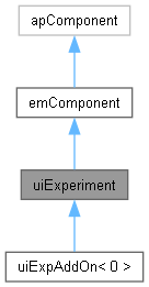
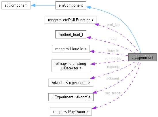
User interface class to perform FDTD calculations. More...
#include <uiexp.h>
Classes | |
| struct | srcdescr_t |
| For storing plane wave/dipole data. More... | |
| struct | tfdescr_t |
| TF region descriptor More... | |
| struct | vtkconf_t |
| VTK configuration struct for conoids. More... | |
Public Member Functions | |
| int | SetMainBlockTypeId (int id=0) |
| Sets the active main block type by its id. | |
| int | SetMainBlockType (const std::string &btypename) |
| Sets the active main block type by its class name. | |
| int | SetVectorizationAxis (int axis) |
| Sets the axis that will be used for (AVX/SSE) vectorization, 0=x, 1=y, 2=z, -1 = automatic setting (usually largest dimension) Vectorization works better for dimensions with uniform geometry (less object boundaries). | |
| int | SetPhases (const std::string &s) |
| Set execution phases: g - just build geometry, c - only calculate, a - only analyse, any other string - everything. | |
| int | SetFirstUpdatedField (int _first_updated_field=1) |
| Sets the first field to be updated by bulk update, 0= E, 1=H may be ignored with warning on some blocks. | |
| int | SetTimers (int use_timers_=1) |
| If timers are used, at the end of the calculation files timers_xxxx.d (xxxx - processor number) will be produced with information of time spend for most important EMTL functions. | |
| int | SetDump (int dump_=1, int dump_format_=GNUPLOT, const iVector_3 &duplicate=iVector_3(1), const iVector_3 &origin=iVector_3(0)) |
| Switch to create files with geometry description format of files is specified by bit flag dump_format: GNUPLOT - simple table that can be read by gnuplot VTK - VTK format that can be read by Paraview. | |
| int | SetGeometryOutput (int flags) |
| Sets flags switching geometry objects output on/off. | |
| int | SetInternalSpace (const Vector_3 &p1_, const Vector_3 &p2_) |
| Sets the position of internal calculation space (PMLs and oblique incidence boundaries are excluded). | |
| int | SetInternalSpace (const Vector_3 &p) |
| Version of the function above with zero left bottom corner. | |
| int | GetInternalSpace (Vector_3 &p1_, Vector_3 &p2_) const |
| Get the position of internal calculation space. | |
| int | GetSpace (Vector_3 &p1_, Vector_3 &p2_) const |
| Get the position of the calculated space (including PMLs, oblique incidence boundaries). | |
| int | SetResolution (valtype dx, valtype dy, valtype dz, valtype courant_=-1) |
| Set mesh step for each axis and Courant factor. | |
| int | SetResolution (valtype dx=-1, valtype courant=-1) |
| Version of the function above with equal mesh step along all axes. | |
| int | SetInternalMeshSize (int nx=-1, int ny=-1, int nz=-1, valtype courant_=-1) |
| Set the axial numbers of mesh steps (for internal space) and the Courant factor. | |
| const int * | GetMeshSize () const |
| Get the axial numbers of mesh steps (for all space). | |
| int | SetCourant (valtype courant_=0.5) |
| Sets the Courant factor. | |
| valtype | GetCourant () const |
| Gets the Courant factor. | |
| int | ConfAutoResolution (valtype lambda=-1, valtype nlambda=15, valtype objr=INF, valtype nobj=1.) |
| Configure settings for automatic mesh step selection: | |
| int | ConfTimeToSize (valtype time2size_=5.) |
| Configure atomatic setting for calculation time: use the time needed to span maximal size of the mesh time2size times. | |
| int | AddMeshBlock (const Vector_3 &p1_, const Vector_3 &p2_, const Vector_3 &dx_, valtype Courant=0.5f, int level=1, int blocktypeid=-1) |
| Adds mesh block overriding the main mesh block in the specified region. | |
| int | SetTime (valtype time, valtype atime=VEC_INFTY) |
| Set/reset calculation time. | |
| int | SetTimeN (int inum_, int finum_=INT_INFTY) |
| Set/reset number of steps. | |
| int | AdjustTimeN (int timesteps) const |
| int | SetFactTimeN (int finum_=INT_INFTY) |
| Set the number of actual steps for the calculation. | |
| int | SetFrequencyRange (int nf_, valtype f1_=0, valtype f2_=0, bool align_freq_=true) |
| Set frequency range (f1,f2) and resolution (number of points nf) inside this range that will be used for all output in frequency/wavelength representation. | |
| int | GetFrequencyRange (int &nf_, valtype &f1_, valtype &f2_) const |
| Gets the current frequency range used in calculation. | |
| int | SetWavelengthRange (int nf_, valtype lambda1_=0, valtype lambda2_=0, bool align_freq_=true) |
| Set wavelength range (lambda1,lambda2) and resolution (number of points nf) inside this range that will be used for all output in frequency/wavelength representation. | |
| int | GetWavelengthRange (int &nf_, valtype &lambda1_, valtype &lambda2_) const |
| Gets the current wavelength range used in calculation. | |
| int | SetBC (int bc_x, int bc_y, int bc_z) |
| Set boundary conditions for corresponding axis. | |
| int | SetOblique (int obl_inum_=1, int obl_dfreq_=1, int obl_dupl_=1, int obl_pml_ncells_0_=20, int obl_ini_wave_=0) |
| Set iterative oblique scheme. | |
| int | SetBorderDelay (int dcoord, valtype sintheta) |
| Set oblique incidence periodic border delay for the specified direction (Hipercone only). | |
| int | SetSmoothing (int smooth=1, Region_3 *reg=NULL) |
| Turn on subpixel smoothing See paper A. | |
| int | SetPMLType (int pmltype, const emPMLFunction &pml_fun_) |
| Set pml type (UPML or CPML) and function by reference which is cloned. | |
| int | SetPMLType (int pmltype=UPML_TYPE, emPMLFunction *pml_fun_=NULL, int managed=1) |
| Set pml type (UPML or CPML) and function default pml type is UPML. | |
| int | ConfPML (int pml_ncells_=10, int add_ncells=0, int nsigma=0, int back_pr1=2, int back_pr2=0, valtype kappa_back_=0) |
| Configure various PML settings: | |
| int | AddPMLBackingLayer () |
| Add PML backing layer with optimal parameters from paper A. | |
| int | AddTFSFPlane (valtype dx, valtype dy, valtype dz, valtype dir=1.f) |
| Creates a source with TFSF planar border. | |
| int | AddTFSFPlane (const Vector_3 &n, const Vector_3 &pos) |
| Creates a source with TFSF planar border. | |
| int | AddTFSFBox (valtype x0, valtype x1, valtype y0, valtype y1, valtype z0, valtype z1) |
| Creates a source with TFSF box as generating surface. | |
| int | AddTFSFBox (const Vector_3 &v0, const Vector_3 &v1) |
| Creates a source with TFSF box as generating surface. | |
| int | SetSignal (emImpulse *impulse, int managed=1, int srcid=-1) |
| Sets the signal form for the generation source given by srcid. | |
| int | SetSignalPtr (emImpulse *impulse, int managed=1, int srcid=-1) |
| A synonym for SetSignal(emImpulse *impulse, int managed=1, int srcid=-1) to be used in Python. | |
| int | SetSignal (const emImpulse &impulse, int srcid=-1) |
| Sets the signal form for the generation source given by srcid. | |
| int | AddRodDipole (const Vector_3 &v0, const Vector_3 &v1, valtype dt=0, valtype amp=1, bool analytic=false, int srcid=-1) |
| Adds a filament dipole to the dipole source. | |
| int | AddPointDipole (const Vector_3 &pos, const Vector_3 &dir, valtype dt=0, valtype amp=1, bool analytic=false, int srcid=-1) |
| Same as AddRodDipole but ensures that a) the dipole has minimal size with respect to mesh resolution; b) may generate waves in all directions. | |
| int | AddTFSFDipole (const Vector_3 &v0, const Vector_3 &d, valtype dt=0, int srcid=-1) |
| Adds a point dipole source to the TF/SF generating surface with given srcid (-1 for default). | |
| int | SetPlaneWave (const Vector_3 &k, const Vector_3 &E, bool analytic=false, int srcid=-1) |
| Assign a plane wave source to the corresponding TF/SF generating surface. | |
| int | SetBraggWave (const Vector_3 &k, const Vector_3 &p, const Vector_3 &kBragg, bool analytic=false, int srcid=-1) |
| Assign a Bragg wave source to the corresponding TF/SF region. | |
| int | UseLambda (int use_lambda_=1) |
| Use wavelength instead of frequency in spectra output. | |
| int | AddDetectorSet (const std::string &name, valtype x0, valtype x1, int nx, valtype y0, valtype y1, int ny, valtype z0, valtype z1, int nz, int mode=0, int srcid=-2) |
| Adds a 3D detector array set. | |
| int | AddDetectorSet (const std::string &name, const Vector_3 &v0, const Vector_3 &v1, const Vector_3 &n=Vector_3(-1.f), int mode=0, int srcid=-2) |
| Same as above in vector form. | |
| int | AddVTKDetectorSet (const std::string &name, const Vector_3 &v0, const Vector_3 &v1, const Vector_3 &rn=Vector_3(-1.f), int ndomains=1) |
| Add detector grid saving fields in parallel VTK format. | |
| int | AddDetectorSet (const std::string &name, const std::vector< Vector_3 > &coords, const std::vector< Vector_3 > &dcoords, int mode=0, int srcid=-2) |
| Adds 3D detector vector. | |
| int | AddNearToFarSet (const std::string &name, const Vector_3 &v0, const Vector_3 &v1, const Vector_3 &origin, valtype R, valtype th0, valtype th1, int thn, valtype fi0, valtype fi1, int fin, int mode=0, valtype resol=1, int srcid=-2) |
| Add detector set for near to far field transformation. | |
| int | AddRTASet (const std::string &name, size_t dir, valtype r_ref, valtype r_tra, valtype rsl=1, int rta_type=0, int srcid=-1) |
| Adds a detector set formed by up to 2 parallel planes, normal to the axis dir. | |
| uiDetector * | GetDetectorSetPtr (const std::string &name) |
| Gets a pointer to detector set, NULL if the set does not exist. | |
| uiDetector * | GetDetectorSet (const std::string &name) |
| Same as GetDetectorSetPtr, but safe: instead of NULL will return a pointer to temporary if detector set does not exist. | |
| int | SetFillMedium (const emMedium &med) |
| Set the filling material for calculated space. | |
| emMedium | GetFillMedium () const |
| Gets the filling material of the calculated space. | |
| int | AddObject (const emMedium &med, Region_3 *regptr, int managed=1, int level=0) |
| Add user 3D object defined by medium properties and region in space. | |
| int | AddObjectPtr (const emMedium &med, Region_3 *regptr, int managed=1, int level=0) |
| A synonym for AddObject(const emMedium &med,Region_3 *regptr,int managed=1, int level=0) to use in Python. | |
| int | AddObject (const emMedium &med, const Region_3 ®, int level=0) |
| Add user 3D object defined by medium properties and region in space. | |
| int | ConfigureTensorMethod (int use_stable=0) |
| Configure settings used by tensor methods (thin_surface, thin_wire, tensor_medium, subpixel_smoothing). | |
| int | Add2DObject (const emMedium &med, const FacetedSurfaceData &surf) |
| Add user object defined by medium properties and a thin 2D surface in space by reference which is cloned. | |
| int | Add2DObject (const emMedium &med, FacetedSurfaceData *surfptr, int managed=1) |
| Add user object defined by medium properties and a thin 2D surface in space by pointer. | |
| int | Add1DObject (const emMedium &med, Wire_3 *wireptr, int managed=1, const Vector_3 &shift=Vector_3()) |
| Add user object defined by medium properties and a thin 1D wire in space If managed flag is 1, the region pointer is managed (deleted by uiExperiment). | |
| int | Add1DObjectPtr (const emMedium &med, Wire_3 *wireptr, int managed=1, const Vector_3 &shift=Vector_3()) |
| A synonym for Add1DObject(const emMedium &med, Wire_3 *wireptr, int managed=1, const Vector_3& shift = Vector_3()) to be used explicitly from Python. | |
| int | Add1DObject (const emMedium &med, const Wire_3 &wire, const Vector_3 &shift=Vector_3()) |
| Add user object defined by medium properties and a thin 1D wire in space. | |
| int | AddBox (const emMedium &med, valtype x0, valtype x1, valtype y0, valtype y1, valtype z0, valtype z1, int level=0) |
| Add a box with corners (x0,y0,z0) and (x1, y1, z1) | |
| int | AddBox (const emMedium &med, const Vector_3 &v0, const Vector_3 &v1, int level=0) |
| Same as above in vector form. | |
| void | SetFarField (int sph_rank, int time_max, int tile_sz=16, const char *path="") |
| Initiates far-field computation in the time domain sph_rank - the rank of the grid in directions built on the basis of the pentakis dodecahedron partition, see http://sv-journal.org/2018-1/09/ time_max - number of time steps tile_sz - tile size (affects calculation speed, for fast far field it can affect accuracy) path - the path along which the fields from the Huygens surface are reset in the .msh format of the aiwlib library (by default they are not reset) nine files with the names [xyz] E [xyz] .msh are created at the specified path, the first letter is the axis of which is orthogonal to the surface face, the last letter is the component. | |
| void | SetFastFarField (double xi_sc, int Nphi, bool phi_interp=true, int approx=1, bool patch_n_phi=false) |
| Initiates fast time-domain far-field computation based on spherical splitting, without calling SetFarField (...) ignored. | |
| void | AddFarFieldRange (Vector_3 n, double theta_min, double theta_max) |
| Adds a selection to the directions in which the far field is considered (axis orientation and theta range of angles). | |
| void | FarFieldFinish (const char *path) |
| Completes the far field calculation. | |
| void | FarFieldLoad (const char *path) |
| Loads the previously calculated far field along the path path, requires the directory path/nt/ and the files path/P.sph and path/info. | |
| void | SetFarFieldBasis (Vector_3 n_theta, Vector_3 n_phi) |
| Specifies the spherical coordinate system in which all post-processing will be performed. | |
| void | FarFieldFourier (const char *path) |
| Carries out the Fourier transform in each direction, the frequency range is determined automatically or can be set explicitly by the SetFrequenceRange (...) method. | |
| void | FarFieldFourier (const char *path, int nf_, valtype f_min, valtype f_max) |
| The same as the FarFieldFourier(const char* path) method, but with an explicit specification of the frequency range. | |
| void | FarFieldDumpDirect (valtype theta, valtype phi, const char *path) |
| Saves along the path "path" in nine columns the dependence of electrical components and Stokes parameters on frequency for an arbitrary direction given by the angles theta, phi. | |
| void | FarFieldSlicePhi (valtype theta, valtype f, int sz, const char *path) |
| Outputs to the file "path" slices (depending on the angle phi) of the field components and Stokes parameters at a given angle theta at frequency f. | |
| void | FarFieldSliceTheta (valtype phi, valtype f, int sz, const char *path) |
| Outputs to the file "path" slices (depending on the angle theta) of the field components and Stokes parameters at a given angle phi at frequency f. | |
| void | FarFieldIntPhi (valtype f, int sz, const char *path) |
| Outputs to the file "path" the integrals over d phi (depending on the angle theta) of the field components and Stokes parameters at the frequency f. | |
| void | FarFieldIntTheta (valtype f, int sz, const char *path) |
| Outputs to the file "path" the integrals over sin(theta) d theta (depending on the angle phi) of the field components and Stokes parameters at the frequency f. | |
| int | SetOutputDir (const char *path) |
| Set directory for text output. | |
| int | SetRawDataDir (const char *path) |
| Set directory for binary output (large files). | |
| virtual int | ClearObjects () |
| Clears all medium objects. | |
| virtual int | BuildDimensions () |
| Calculates full mesh dimensions, space and time steps according to the communicated settings: boundary conditions, internal space size and resolution. | |
| int | AlignWithField (Vector_3 &vec, int ftype, int dir, const Vector_3 &shift=Vector_3()) const |
| Aligns the vector to coinside with the nearest node of the field of given type and direction: ftype =0 for E, ftype =1 for H, dir =0,1,2 for x,y,z. | |
| const Vector_3 & | GetSpaceStep () const |
| Gets mesh space step (valid after BuildDimensions call). | |
| valtype | GetTimeStep () const |
| Gets mesh time step (valid after BuildDimensions call). | |
| virtual int | BuildGeometry () |
| Intialize EMTL objects corresponding to calculated space, PML, sources, medium regions, detectors. | |
| virtual int | BuildMesh () |
| Allocate memory for EMTL objects and fill all necessary data (coefficients in finite difference scheme etc.). | |
| int | Calculate (valtype time, valtype ftime=VEC_INFTY) |
| Performs FDTD simulation for given time. | |
| int | CalculateN (int inum_, int finum_=INT_INFTY) |
| Performs FDTD simulation for given number of steps. | |
| virtual int | Reset (int keep_setup=0x7) |
| Resets the experiment to setup phase, cleaning the calculation mesh. | |
| void | RemoveBinaries (bool rb=true) |
| Remove binary detector files in desctructor. | |
| void | SetBalancedDecomposition (int balanced_=1, const Vector_3 &balanced_dx_=0, const method_load_t &load_=method_load_t()) |
| Perform balanced domain decomposition. | |
| int | SetMeshBlockParam (const std::string &key, valtype value, int btypeid=-1, int blockid=-1) |
| Sets block-specific parameters in the from ("key", value). | |
| int | DumpMedium (const char *fname, const emMedium &med, valtype lf1=-1, valtype lf2=-1, valtype ldf=0) const |
| Writes the frequency (wavelength) dependence of the medium. | |
| int | DumpFields (const char *path, iVector_3 bmin=iVector_3(0), iVector_3 bmax=iVector_3(0), int field_mask=63) const |
| Saves the current field configuration in the .msh binary format of the aiwlib library, see http://sv-journal.org/2018-1/09/ six frames are saved in the file along the path path - Ex, Ey, Ez, Hx, Hy, Hz, cell type float. | |
| int | DumpCoeffs (const char *path, iVector_3 bmin=iVector_3(0), iVector_3 bmax=iVector_3(0), int coeff_mask=4095) const |
| Stores the distribution of coefficients in the binary .msh format of the aiwlib library, see http://sv-journal.org/2018-1/09/ twelve frames are saved in the file along the path path - c1Ex, c2Ex, c1Ey, c2Ey, c1Ez, c2Ez, c1Hx, c2Hx, c1Hy, c2Hy, c1Hz, c2Hz, cell type float | |
| int | DumpFix (const char *path, iVector_3 bmin=iVector_3(0), iVector_3 bmax=iVector_3(0), int EH_mask=3) const |
| Stores the distribution of fixes (bit masks) in the .msh binary format of the aiwlib library, see http://sv-journal.org/2018-1/09/ one frame is saved in the file along the path path, cell type is float. | |
| int | DumpMat (const char *path, iVector_3 bmin=iVector_3(0), iVector_3 bmax=iVector_3(0), int EH_mask=3) const |
| Saves the distribution of materials (corresponding to ID on the computational grid) in the binary .msh format of the aiwlib library, see http://sv-journal.org/2018-1/09/ one frame is saved in the file along the path path, cell type is float. | |
| int | CalcN (int inum_, int finum_=INT_INFTY) |
| Performs FDTD simulation for given number of steps (for python interface). | |
| int | Calc (valtype time, valtype ftime=VEC_INFTY) |
| Performs FDTD simulation for given time (for python interface). | |
| valtype | GetComputeRate (bool renew=false) |
| Gets current average compute rate in GYeeCells/s. | |
| void | SetTextureParams (valtype k=1., valtype shift=0., valtype k_disp=1., valtype shift_disp=0.) |
| Underlying media may be displayed in QPLT format by overimposing them on the fields. | |
 Public Member Functions inherited from emComponent Public Member Functions inherited from emComponent | |
| emDump * | GetEmDumper () |
| This function insures that the returned dumper is of true emDumper type. | |
Protected Types | |
| enum | PHASE_FLAGS |
| Execution phases. | |
| enum | RES_MODES |
| What defines resolution. | |
| enum | { } |
| Source types. More... | |
| enum | |
| TF region types. | |
| typedef mngptr< emImpulse > | impulse_t |
| if true, exit from function Calculate | |
Protected Member Functions | |
| int | check_phase (int lim_phase) |
| Check if current phase exceeds lim_phase. | |
| int | fix_frequency_range () |
| Make frequency range f1, f2, nf aligned with . | |
| int | adjust_freq_steps (int inum_, int finum_) |
| Adjust steps number and frequency range to container. | |
| void | DetStartNextFileRecord (int inum, int nobl, int depth, int filter=0x3) |
| void | DetCompleteNextFileRecord (int inum, int nobl, int depth=0, int filter=0x3) |
| Puts the updated interpolated values into file. | |
| int | add_dipole (const Vector_3 &v0, const Vector_3 &v1, valtype dt, valtype amp, int srcid, int type=0, bool analytic=false) |
| Internal function for adding dipoles, type=0 – rod dipole, type=1 – point dipole. | |
| void | preset_box_detector (uiDetector *det, Vector_3 &n, const Vector_3 &v0, const Vector_3 &v1, int mode, int srcid) |
| Auxilliary function to configure box type detectors (including VTK) | |
Protected Attributes | ||
| int | sync_hsteps = 2 | |
| global synchronization level, to be tuned | ||
| int | phase | |
| Current phase. | ||
| bool | strict_phase | |
| Whether to forbid to pass to the previous phase from the subsequent. | ||
| int | exe_phases | |
| Phases which will be fulfilled (bit flag). | ||
| int | analytic_geometry_analysis | |
| Do geometrical analysis analitiaclly, without contours loop. | ||
| double | sys_t0 | |
| Program start time. | ||
| double | sys_tmax | |
| Mesh data will be saved in binary files each sys_tsave interval and after sys_tmax time from start. | ||
| int | use_timers | |
| Whether to use timers. | ||
| struct { | ||
| } | tid | |
| The id of timers which are responsible for phases of experiment. | ||
| int | dump | |
| Whether to create files with the set bodies, detectors for review in the gnuplot. | ||
| int | dump_format | |
| see VISUAL_FORMATS (to dump in gnuplot or vtk format). | ||
| iVector_3 | dump_dup = iVector_3(1) | |
| how many elementary cells are duplicated in each direction for dump | ||
| iVector_3 | dump_dup_orig = iVector_3(0) | |
| duplication origin | ||
| int | vec_axis | |
| The axis that will be used for vectorization, -1 = automatic setting (usually largest dimension). | ||
| Vector_3 | size | |
| The calculated space position and size. | ||
| Vector_3 | isize | |
| The same for internal space. | ||
| int | N [3] | |
| Mesh steps number. | ||
| Vector_3 | dr | |
| Mesh step in each direction. | ||
| valtype | dt | |
| Time step. | ||
| valtype | courant | |
| The factor of Courant. | ||
| int | first_updated_field | |
| The first field to be updated by bulk update, 0= E, 1=H ignored with warning on some block types. | ||
| int | inum =0 | |
| Number of time steps. | ||
| int | finum =0 | |
| Actual steps number. | ||
| int | obl_inum | |
| Number of oblique incidence iterations. | ||
| int | obl_dfreq | |
| Detectors work each obl_dfreq oblique iteration and last iteration. | ||
| iVector_3 | bc | |
| Boundary conditions for axial directions. | ||
| Vector_3 | obl_k | |
| oblique incidence direction. If nonzero, iterative scheme is applied. | ||
| valtype | obl_ncells | |
| Split between writing and generating boundaries at oblique incidence. | ||
| valtype | obl_pml_ncells | |
| Distance between oblique boundaries and PML. | ||
| valtype | obl_pml_ncells_0 | |
| Distance between oblique boundaries and PML minus obl_ncells. | ||
| int | past_flag | |
| Used data from the same iteration for 'past' oblique boundaries. | ||
| int | obl_dupl | |
| How many times dublicate periodic cell along oblique direction in oblique incidence case. | ||
| int | obl_ini_wave | |
| Use all oblique boundaries as TF/SF generating surface on the first oblique iteration. | ||
| bool | no_auto_oblique = false | |
| Do not automatically swithc to oblique incidence when obl_k is pointing towards PBC. | ||
| int | delay_coord = -1 | |
| Direction of PBC with delay (Hipercone only). | ||
| valtype | df | |
| The bottom and top frequencies in investigated spectrum, step on frequency. | ||
| bool | align_freq | |
| Maximally align frequencies with the internal range. | ||
| int | nf | |
| Quantity of investigated frequencies. | ||
| bool | on_fly | |
| Whether use Fourier-on-flight instead of FFDT. | ||
| int | use_lambda | |
| Use lambda instead of frequency in output text files. | ||
| int | flux_out | |
| What to output in a rta file (see outFLUX). | ||
| int | fft_dir | |
| Signs in the exponent for Fourier transformation exp(+/-iwt+/-ikx). | ||
| int | tf_dir | |
| Sign in the exponent for Fourier transformation exp(+/-iwt). | ||
| int | xk_dir | |
| Sign in the exponent for Fourier transformation exp(+/-ikx). | ||
| int | use_smooth | |
| Whether to use subpixel smoothing. | ||
| Region_3 * | sm_reg | |
| If defined, subpixel smoothing works only inside this region. | ||
| int | pml_type | |
| NPML, UPML or CPML. | ||
| mngptr< emPMLFunction > | pml_fun | |
| How pml parameters (sigma, kappa) depend on depth inside PML. | ||
| int | pml_ncells | |
| Number of mesh steps inside PML. | ||
| int | pml_nspace | |
| Number of mesh steps between internal space and PML. | ||
| int | pml_nsigma | |
| Number of mesh steps in PML before back PML layer. | ||
| int | back_profile [2] | |
| The flags used in back PML layer. | ||
| valtype | kappa_back | |
| Maximal kappa of back PML layer. | ||
| int | cpml_orot | |
| Whether to use modification of a block internal cycle for CPML. | ||
| int | prl_anls | |
| Whether to do the parallel analysis (in case of use Fourier-on-flight). | ||
| int | wf | |
| Whether to use a cycle with vectorization. | ||
| bool | remove_binaries | |
| If true, remove binary detector files in desctructor. | ||
| int | mpi_transfers | |
| If 0, no MPI-transfers will be sent (test option). | ||
| iVector_3 | ndomains | |
| Arguments of MakeBoxDomains(). | ||
| int | balanced | |
| Perform balanced domain decomposition. | ||
| int | balanced_ppn | |
| If more than 1, then number of processors in sub-domain. | ||
| int | ppn_weight | |
| Perform balanced decomposition for super-domains. | ||
| Vector_3 | balanced_dx | |
| Space step used in grid for domain domain decomposition. | ||
| method_load_t | load | |
| Load coefficients for different methods. | ||
| std::map< int, impulse_t > | impulses | |
| Default impulse form. | ||
| valtype | imp_ampl | |
| Default signal amplitude. | ||
| valtype | tscale | |
| Scaling default Berenger pulse. | ||
| mngptr< Liouville > | liouville | |
| Energy levels and dipole moment of atoms. | ||
| std::vector< tfdescr_t > | tfregions | |
| TFSF region descriptions. | ||
| refmap< std::string, uiDetector > | detectors | |
| detector descriptions. string is used to make output text files | ||
| emMedium | MExt | |
| Number of TF regions. | ||
| refvector< regdescr_t > | regions | |
| Region descriptions. | ||
| std::map< int, tensor_med_t > | eps_tensors | |
| Dielectric tensors assigned to selected media. | ||
| int | use_stable | |
| Stability flag for tensor methods. | ||
| int | time_limit | |
| Variable used to indicate calculation time limits: -1 = automatic by internal space size, 1 = use preset inum, 0 = in the course of calculation. | ||
| valtype | time2size | |
| Variable for setting calculation time to maximal mesh size ratio (default is 5). | ||
| int | topthreads | |
| Topthreads number for conoids. | ||
| int | prank_lo | |
| Runtime parallel rank for conoids prank_lo is the lowest rank on which we calculate conoids in parallel. | ||
| int | grid_lowrank | |
| lowest rank to use in conetur grid (default is 3, optimal rank is 6). | ||
| bool | vtkconf_set | |
| VTK configuration flag. True if configuration was set. | ||
| int | interm_detectors | |
| Number of detectors for which intermediate analysis was requested. | ||
| int | main_blockid | |
| Set blockid to use as a global main mesh. | ||
| int | s_it | |
| Persistent step and oblique iteration counters. | ||
| double | s_dtime | |
| Persistent start time of the first iteration. | ||
| std::map< std::string, block_param_t > | bparammap | |
| map to pass parameters to blocks | ||
| int | analyze_flags = ~0 | |
| Analyze flags to be passed to container (for testing only) | ||
| int | omp_max_threads = -1 | |
| Override max_threads for OMP, used to tune OMP performance, -1 means no override. | ||
| int | gdumpflags = dmpMAINREG | dmpTFSFREG | dmpPMLREG | dmpMEDIAREG | dmpMPIBLOCKS | dmpDETPOINTS | dmpBLOCKREG | |
| default flags for dumping geometry objects | ||
Friends | |
| class | uiDetector |
Detailed Description
User interface class to perform FDTD calculations.
Below you can find all settings of uiExperiment. Some of them can be changed by functions defined in public scope, some of them have optimal default values and there is no need to change them.
Member Enumeration Documentation
◆ anonymous enum
|
protected |
Source types.
Member Function Documentation
◆ Add1DObject()
| int uiExperiment::Add1DObject | ( | const emMedium & | med, |
| Wire_3 * | wireptr, | ||
| int | managed = 1, |
||
| const Vector_3 & | shift = Vector_3() |
||
| ) |
Add user object defined by medium properties and a thin 1D wire in space If managed flag is 1, the region pointer is managed (deleted by uiExperiment).
◆ Add1DObjectPtr()
|
inline |
A synonym for Add1DObject(const emMedium &med, Wire_3 *wireptr, int managed=1, const Vector_3& shift = Vector_3()) to be used explicitly from Python.
Add user object defined by medium properties and a thin 1D wire in space If managed flag is 1, the region pointer is managed (deleted by uiExperiment).
◆ Add2DObject()
| int uiExperiment::Add2DObject | ( | const emMedium & | med, |
| FacetedSurfaceData * | surfptr, | ||
| int | managed = 1 |
||
| ) |
Add user object defined by medium properties and a thin 2D surface in space by pointer.
If managed flag is 1, the region pointer is managed (deleted by uiExperiment).
◆ AddDetectorSet() [1/2]
| int uiExperiment::AddDetectorSet | ( | const std::string & | name, |
| const Vector_3 & | v0, | ||
| const Vector_3 & | v1, | ||
| const Vector_3 & | n = Vector_3(-1.f), |
||
| int | mode = 0, |
||
| int | srcid = -2 |
||
| ) |
Same as above in vector form.
Same as above, but resolution can be less than 1. If n[i] < 0, then - n[i] value is treated as number of mesh steps per detector in the specific direction. This number can be less than 1, for example, -0.5 means that two detectors will be set up per mesh step
◆ AddDetectorSet() [2/2]
|
inline |
Adds a 3D detector array set.
The name is used for forming the filename. If n[i]<0, then -n[i] value is treated as number of mesh steps per detector in the specific direction. If n[i]=INT_INFTY or n[i]=-1, then detector array resolution for this direction will be the same as mesh resolution.
If any of grid counts n[i]<=1, n[i]=1 is assumed for this direction. mode is a bit flag which may be | combination of the following
DET_POINT (=0, default) - a separate file is formed for each space point
DET_TSTEP - a file containing the grid is formed for each time or frequency step (for animations)
DET_MESH (default) - detector records data from FDTD mesh
DET_SRC - detector calculates the fields data at self location according to the
signal form of the source with given id (-1 for default source)
the source signal is assumed to propagate in the uniform medium filling the calculated space (see SetFillMedium())
DET_F - makes Fourier transform in frequency (for POINT detectors only)
(NOT IMPLEMENTED)DET_K - makes Fourier transform in k (for POINT detectors, k-transform is performed for directions with n>2 only, a separate file is written for each k)
srcid, is valid with DET_SRC mode only, used to specify the source for analytic detector, srcid<0 uses the default source
- Returns
- the id of the detector.
◆ AddFarFieldRange()
|
inline |
Adds a selection to the directions in which the far field is considered (axis orientation and theta range of angles).
By default, the calculation is performed over the entire sphere.
◆ AddMeshBlock()
|
inline |
Adds mesh block overriding the main mesh block in the specified region.
The main block with id =0 is added automatically. Parameter blocktypeid indicates the block type to add. Default block type (-1) is the same as the main block type.
- Returns
- the id>0 of the added block
◆ AddNearToFarSet()
| int uiExperiment::AddNearToFarSet | ( | const std::string & | name, |
| const Vector_3 & | v0, | ||
| const Vector_3 & | v1, | ||
| const Vector_3 & | origin, | ||
| valtype | R, | ||
| valtype | th0, | ||
| valtype | th1, | ||
| int | thn, | ||
| valtype | fi0, | ||
| valtype | fi1, | ||
| int | fin, | ||
| int | mode = 0, |
||
| valtype | resol = 1, |
||
| int | srcid = -2 |
||
| ) |
Add detector set for near to far field transformation.
The box around v0, v1 is used as a closed surface to measure fields. The resolution of the surface is controlled by resol parameter the same way as in AddFluxSet(). The far fields are obtained in frequency domain during the analyzis phase at the points listed in far_detectors vector. These points must lie outside the measurement surface arbitrarily far from it. They do not need to lie inside the computational domain. Supported modes are DET_F, DET_K, DET_TSTEP. Detector name is used to form the file names for recording output, the spectra for far detectors is given in file ...
◆ AddObject() [1/2]
|
inline |
Add user 3D object defined by medium properties and region in space.
Level defines priority if some objects are intersected: at the intersection between two objects, the object with higher priority (level) will be considered, objects with smaller prioirty will be ingnored.
◆ AddObject() [2/2]
|
inline |
Add user 3D object defined by medium properties and region in space.
If managed flag is 1, the region pointer is managed (deleted by uiExperiment) Level defines priority if some objects are intersected: at the intersection between two objects, the object with higher priority (level) will be considered, objects with smaller prioirty will be ingnored.
◆ AddObjectPtr()
|
inline |
A synonym for AddObject(const emMedium &med,Region_3 *regptr,int managed=1, int level=0) to use in Python.
Add user 3D object defined by medium properties and region in space. If managed flag is 1, the region pointer is managed (deleted by uiExperiment) Level defines priority if some objects are intersected: at the intersection between two objects, the object with higher priority (level) will be considered, objects with smaller prioirty will be ingnored.
◆ AddPMLBackingLayer()
|
inline |
Add PML backing layer with optimal parameters from paper A.
Deinega and I. Valuev, «Long-time behavior of PML absorbing boundaries for layered periodic structures», Comp. Phys. Comm. 182, 149 (2011).
◆ AddPointDipole()
| int uiExperiment::AddPointDipole | ( | const Vector_3 & | pos, |
| const Vector_3 & | dir, | ||
| valtype | dt = 0, |
||
| valtype | amp = 1, |
||
| bool | analytic = false, |
||
| int | srcid = -1 |
||
| ) |
Same as AddRodDipole but ensures that a) the dipole has minimal size with respect to mesh resolution; b) may generate waves in all directions.
This fixes the problem of a filament dipole that is not long enough and not properly aligned with the grid: such dipole may work only in the one major direction. The current function sets in fact 3 filaments aligned with the grid with lengths of 1.5*dr[i] and with the intensities corresponding to the dipole directional contributions.
- Parameters
-
[in] dir dipole direction (normalized automatically), [in] pos dipole position, other parameters and return values are the same as in AddRodDipole. Point dipoles may be mixed with rod dipooles in the same dipole source.
◆ AddRodDipole()
| int uiExperiment::AddRodDipole | ( | const Vector_3 & | v0, |
| const Vector_3 & | v1, | ||
| valtype | dt = 0, |
||
| valtype | amp = 1, |
||
| bool | analytic = false, |
||
| int | srcid = -1 |
||
| ) |
Adds a filament dipole to the dipole source.
The filament containing current has zero thickness and defined ends. The signal is generated by mesh contours that are crossed by the filament. Rod/point dipoles use the signal set for their source or default signal for operation. They are mesh point sources and do not require TF/SF generating surfaces. The parameters define positions of the two current filament ends and the time shift for the signal. If srcid is -1, then tries to locate the first source containing rod/point dipoles and adds the dipole there (creates new dipole source if no such sources found). If srcid is not -1, and belongs to the existing rod/point dipole source, adds the dipole to the indicated source. If srcid belongs to the source of different type (f.e. TFSF), then the error message is given.
- Returns
- the id of the source that this dipole belongs to.
-
<0 in case of error (wrong source type or no source found). See also AddPointDipole.
◆ AddRTASet()
| int uiExperiment::AddRTASet | ( | const std::string & | name, |
| size_t | dir, | ||
| valtype | r_ref, | ||
| valtype | r_tra, | ||
| valtype | rsl = 1, |
||
| int | rta_type = 0, |
||
| int | srcid = -1 |
||
| ) |
Adds a detector set formed by up to 2 parallel planes, normal to the axis dir.
The name is used for forming the filename. This set is mainly used to obtain the Relection, Transmission, Adsorbtion spectra. dir defines the planes direction: 0=x, 1=y, 2=z; r_ref, r_tra are the position of the planes for measuring reflected and transmitted waves. Incident wave is measured by analytical source at the plane for transmitted wave The positions are counted along the plane normal, starting from the container origin. If any of the positions is outside the container, the corresponding plane is not added. rsl defines the resolution of detectors in comparison to mesh step (detectors per step) in each plane. The TF/SF generating plane should be placed between r_ref and r_tra for proper operation.
If DET_SRC flag is specified in the type, the incident detector plane r_inc uses calculated signal form of the source with given id (-1 for default source). The source signal is assumed to propagate in the uniform medium filling the calculated space (see SetFillMedium()).
If DET_NRM flag is specified in the type, the output contains reflection and adsorption coefficients: the 'refl' and 'tra' columns are normalized by the incident wave ('inc' column)
- Returns
- the id of the detector.
◆ AddTFSFBox() [1/2]
| int uiExperiment::AddTFSFBox | ( | const Vector_3 & | v0, |
| const Vector_3 & | v1 | ||
| ) |
Creates a source with TFSF box as generating surface.
The parameters define two box corners.
- Returns
- srcid of the TFSF region.
◆ AddTFSFBox() [2/2]
|
inline |
Creates a source with TFSF box as generating surface.
The parameters define two box corners.
- Returns
- srcid of the TFSF region.
◆ AddTFSFDipole()
| int uiExperiment::AddTFSFDipole | ( | const Vector_3 & | v0, |
| const Vector_3 & | d, | ||
| valtype | dt = 0, |
||
| int | srcid = -1 |
||
| ) |
Adds a point dipole source to the TF/SF generating surface with given srcid (-1 for default).
TF/SF dipoles use the signal set for the corresponding TF/SF region (or default one) for operation The parameters define position, dipole moment, time shift and the TF/SF region id. If srcid is <0, the first setup TFSF source is used.
- Returns
- the id of the source that this dipole has been added to.
◆ AddTFSFPlane() [1/2]
| int uiExperiment::AddTFSFPlane | ( | const Vector_3 & | n, |
| const Vector_3 & | pos | ||
| ) |
Creates a source with TFSF planar border.
The parameters n and pos define the plane normal and starting point. The normal points to the TF region.
- Returns
- the srcid of the TFSF region.
◆ AddTFSFPlane() [2/2]
| int uiExperiment::AddTFSFPlane | ( | valtype | dx, |
| valtype | dy, | ||
| valtype | dz, | ||
| valtype | dir = 1.f |
||
| ) |
Creates a source with TFSF planar border.
sources.
To setup a radiation source in EMTL UI one has to specify 3 components for each source: source type, TF region, time signal form. Source types can be: PlaneWave, BraggWave, AddPointDipole, TFSFDipole, RodDipole TF regions can be: TF/SF plane, TF/SF box, void Time signal is set as a pointer to emImpulse class. Most of the sources except for RodDipole imply TF/SF generation technique and require a TF region. For the RodDipole TF region is not used. To specify the signal form for the TF/SF type sources use the functions AddTFSFPlane, AddTFSFBox. The integer ids specified as arguments to these functions are reserved for future use and should have default value srcid=-1 for this version.
The parameters dx, dy, dz define the intersection points of the plane with the axes. For the plane parellel to the axis INF should be used. Positive dir corresponds to the TF being to the left of crossings for each axis.
- Returns
- the srcid of the TFSF region.
- srcid (указатель) на созданную область TFSF.
◆ AddVTKDetectorSet()
| int uiExperiment::AddVTKDetectorSet | ( | const std::string & | name, |
| const Vector_3 & | v0, | ||
| const Vector_3 & | v1, | ||
| const Vector_3 & | rn = Vector_3(-1.f), |
||
| int | ndomains = 1 |
||
| ) |
Add detector grid saving fields in parallel VTK format.
If n[i]<0, then -n[i] value is treated as number of mesh steps per detector in the specific direction. If n[i]=INT_INFTY or n[i]=-1, then detector array resolution for this direction will be the same as mesh resolution.
This number can be less than 1, for example, n[i]=-0.5 means that two detectors will be set up per mesh step Parameter ndomains is the number of pieces for the VTK parallel format.
◆ AdjustTimeN()
|
inline |
- Returns
- the number of steps value that is greater or equal than timesteps and is a multiple of synchronization steps Valid values are expected after BuildMesh() is called.
◆ AlignWithField()
| int uiExperiment::AlignWithField | ( | Vector_3 & | vec, |
| int | ftype, | ||
| int | dir, | ||
| const Vector_3 & | shift = Vector_3() |
||
| ) | const |
Aligns the vector to coinside with the nearest node of the field of given type and direction: ftype =0 for E, ftype =1 for H, dir =0,1,2 for x,y,z.
Parameter shift is used to shift the aligned vector by corresponding value in meshsteps dr[i]*shift[i].
- Returns
- >0 on success, <0 otherwise (vec unchanged) (valid after BuildDimensions call).
◆ BuildDimensions()
|
virtual |
Calculates full mesh dimensions, space and time steps according to the communicated settings: boundary conditions, internal space size and resolution.
If autoresolution is used then signal wavelength, objects sizes are taken into account.
◆ Calc()
|
inline |
Performs FDTD simulation for given time (for python interface).
- Returns
- 1 on success, <0 otherwise.
◆ CalcN()
|
inline |
Performs FDTD simulation for given number of steps (for python interface).
- Returns
- 1 on success, <0 otherwise.
◆ Calculate()
| int uiExperiment::Calculate | ( | valtype | time, |
| valtype | ftime = VEC_INFTY |
||
| ) |
Performs FDTD simulation for given time.
- Returns
- 1 on success, <0 otherwise.
◆ CalculateN()
| int uiExperiment::CalculateN | ( | int | inum_, |
| int | finum_ = INT_INFTY |
||
| ) |
Performs FDTD simulation for given number of steps.
- Returns
- 1 on success, <0 otherwise.
◆ ConfAutoResolution()
|
inline |
Configure settings for automatic mesh step selection:
- Parameters
-
[in] lambda - characteristic wavelength (-1 means try to get from the used source). [in] nlambda - minimal number of steps per lambda. [in] objr - characteristic minimal object size (INF means try to get from actual objects). [in] nobj - minimal number of steps per objr.
◆ ConfigureTensorMethod()
| int uiExperiment::ConfigureTensorMethod | ( | int | use_stable = 0 | ) |
Configure settings used by tensor methods (thin_surface, thin_wire, tensor_medium, subpixel_smoothing).
Implements symmetric interpolation according to Gregory R Werner, John R Cary "A stable FDTD algorithm for non-diagonal, anisotropic dielectrics", Journal of Computational Physics 226 (2007) 1085-1101.
- Parameters
-
[in] use_stable 1= using the stable version (works now for thin surface only), 0 = use old version
- Returns
- 1 if OK, <0 otherwise
◆ ConfPML()
|
inline |
Configure various PML settings:
- Parameters
-
[in] add_ncells - additional void cells between PMLs and internal space.
◆ ConfTimeToSize()
|
inline |
Configure atomatic setting for calculation time: use the time needed to span maximal size of the mesh time2size times.
The step counter and calculation time value is reset to zero by this call.
◆ DetCompleteNextFileRecord()
|
protected |
Puts the updated interpolated values into file.
For asynchronous updates, puts the previously stored asynchrous values of
- Parameters
-
depth into file.
◆ DetStartNextFileRecord()
|
protected |
- Parameters
-
filter 0= none, 1=sync only, 2= async only, 3=all
◆ DumpFields()
| int uiExperiment::DumpFields | ( | const char * | path, |
| iVector_3 | bmin = iVector_3(0), |
||
| iVector_3 | bmax = iVector_3(0), |
||
| int | field_mask = 63 |
||
| ) | const |
Saves the current field configuration in the .msh binary format of the aiwlib library, see http://sv-journal.org/2018-1/09/ six frames are saved in the file along the path path - Ex, Ey, Ez, Hx, Hy, Hz, cell type float.
◆ DumpFix()
| int uiExperiment::DumpFix | ( | const char * | path, |
| iVector_3 | bmin = iVector_3(0), |
||
| iVector_3 | bmax = iVector_3(0), |
||
| int | EH_mask = 3 |
||
| ) | const |
Stores the distribution of fixes (bit masks) in the .msh binary format of the aiwlib library, see http://sv-journal.org/2018-1/09/ one frame is saved in the file along the path path, cell type is float.
◆ DumpMat()
| int uiExperiment::DumpMat | ( | const char * | path, |
| iVector_3 | bmin = iVector_3(0), |
||
| iVector_3 | bmax = iVector_3(0), |
||
| int | EH_mask = 3 |
||
| ) | const |
Saves the distribution of materials (corresponding to ID on the computational grid) in the binary .msh format of the aiwlib library, see http://sv-journal.org/2018-1/09/ one frame is saved in the file along the path path, cell type is float.
◆ DumpMedium()
| int uiExperiment::DumpMedium | ( | const char * | fname, |
| const emMedium & | med, | ||
| valtype | lf1 = -1, |
||
| valtype | lf2 = -1, |
||
| valtype | ldf = 0 |
||
| ) | const |
Writes the frequency (wavelength) dependence of the medium.
- M dielectic and magnetic permitivities into gnuplot-friendly text file
- fname. Uses the range [lf1, lf2] with step dlf, if not specified uses the current frequency (wavelength) range of uiExperiment. Takes UseLambda setting into account, when interpreting the range as ferquency or wavelength.
- Returns
- >0 on success, <=0 otherwise.
◆ FarFieldDumpDirect()
|
inline |
Saves along the path "path" in nine columns the dependence of electrical components and Stokes parameters on frequency for an arbitrary direction given by the angles theta, phi.
The FarFieldFourie method must be called first.
◆ FarFieldFinish()
|
inline |
Completes the far field calculation.
A directory named nt is created along the path "path", in which a number of files are created with names like "direction-ID" .dat. In each file path /nt/XXXX.dat in the collateral starting with symbols #: the direction and column names are saved, followed by four columns of time and three components for the next field. In addition, a file path/P.sph is created with an integral over time Poynting vector in the format of the aiwlib library (for viewing, use the aiwlib viewer) and file path/P.dat with similar 3D polar pattern for viewing in gnuplot (contains the coordinates of the edges of the triangular mesh in spherical coordinates, the Poynting vector is used as the modulus of the radius) The file path/info contains service information about calculating the far field, which may be needed for further load from disk.
◆ FarFieldFourier()
|
inline |
Carries out the Fourier transform in each direction, the frequency range is determined automatically or can be set explicitly by the SetFrequenceRange (...) method.
Along the path "path" directories are created with the names path+"nf/" and 'path+"sph/". In the directory path+"nf/" a series of files with names like "ID-direction".dat, in each file in the collateral beginning with symbols #: the direction and column names are saved, further in nine columns the frequency, real and imaginary parts of the Fourier transforms of the longitudinal and transverse components of the electric field are four Stokes parameters. A series of XXXX.sph files is created in the path+"sph /" directory, where XXXX is the frequency number. Each file stores four Stokes parameters in the form of four sequential frames in aiwlib library format, you can use the uplt viewer to view it.
◆ FarFieldIntPhi()
|
inline |
Outputs to the file "path" the integrals over d phi (depending on the angle theta) of the field components and Stokes parameters at the frequency f.
◆ FarFieldIntTheta()
|
inline |
Outputs to the file "path" the integrals over sin(theta) d theta (depending on the angle phi) of the field components and Stokes parameters at the frequency f.
◆ FarFieldLoad()
|
inline |
Loads the previously calculated far field along the path path, requires the directory path/nt/ and the files path/P.sph and path/info.
◆ FarFieldSlicePhi()
|
inline |
Outputs to the file "path" slices (depending on the angle phi) of the field components and Stokes parameters at a given angle theta at frequency f.
◆ FarFieldSliceTheta()
|
inline |
Outputs to the file "path" slices (depending on the angle theta) of the field components and Stokes parameters at a given angle phi at frequency f.
◆ fix_frequency_range()
|
protected |
Make frequency range f1, f2, nf aligned with
.
- minimal frequency step, which is defined as 1/T, where T - number of analyzed time steps (inum_det)
- and maximal frequency (or minimal wavelength lambda_min), whcih statisfies the condition 10 mesh steps on lambda_min.
◆ GetComputeRate()
|
inline |
Gets current average compute rate in GYeeCells/s.
The rate is averaged over all computations performed so far before renewal. If renew is true, the averaging is restarted from scratch.
◆ GetDetectorSet()
| uiDetector * uiExperiment::GetDetectorSet | ( | const std::string & | name | ) |
Same as GetDetectorSetPtr, but safe: instead of NULL will return a pointer to temporary if detector set does not exist.
The temporary will not be stored and used, so changing the temporary detector set will not have any effect.
◆ GetFrequencyRange()
|
inline |
Gets the current frequency range used in calculation.
The range becomes fully actualized after a call to BuildDimensions(). Fills in the input parameters which are the same as in SetFrequencyRange().
◆ GetWavelengthRange()
|
inline |
Gets the current wavelength range used in calculation.
The range becomes fully actualized after a call to BuildDimensions(). Fills in the input parameters which are the same as in SetWavelengthRange().
◆ Reset()
|
virtual |
Resets the experiment to setup phase, cleaning the calculation mesh.
keep_setup bits:
0x1 – keep sources (impulses+tfregions+sources)
0x2 – keep medium regions (objects)
0x4 – keep detectors
◆ SetBC()
|
inline |
Set boundary conditions for corresponding axis.
Flags may be BC_PER (periodic), BC_PML (absorbing), BC_REFL (reflecting) If oblique direction k is set, the periodic borders not parallel to k are used for itrative recording. Default boundary conditions: periodic in the x-,y-, PML in z-direction.
◆ SetBorderDelay()
|
inline |
Set oblique incidence periodic border delay for the specified direction (Hipercone only).
Delay is positive in posditive direction (assuming incidence angle theta >0).
◆ SetBraggWave()
| int uiExperiment::SetBraggWave | ( | const Vector_3 & | k, |
| const Vector_3 & | p, | ||
| const Vector_3 & | kBragg, | ||
| bool | analytic = false, |
||
| int | srcid = -1 |
||
| ) |
Assign a Bragg wave source to the corresponding TF/SF region.
kBragg defines the (surface) Bragg vector, other parameters are the same as in AddPlaneWave TODO: define Bragg vector via (nx,ny) for the cell
◆ SetCourant()
|
inline |
Sets the Courant factor.
Default value 0.5
◆ SetDump()
|
inline |
Switch to create files with geometry description format of files is specified by bit flag dump_format: GNUPLOT - simple table that can be read by gnuplot VTK - VTK format that can be read by Paraview.
Prameter duplicate specifies how many elementary cells will be duplicated in output. The origin (lowest index cell) for duplicating can be specified by origin. The experiment boundary conditions are used when duplicating, even BCs (PEM boundary) result in mirroring the geometry structures.
◆ SetFactTimeN()
|
inline |
Set the number of actual steps for the calculation.
- Parameters
-
finum_ – actual steps number. If this is less than inum, then in (finum, inum) mesh is not updated, but detectors are still working. It can be used to artificially increase of calculation duration and therefore frequency resolution. Infinity by default. The step counter and calculation time value is reset to zero by this call.
◆ SetFarField()
| void uiExperiment::SetFarField | ( | int | sph_rank, |
| int | time_max, | ||
| int | tile_sz = 16, |
||
| const char * | path = "" |
||
| ) |
Initiates far-field computation in the time domain
sph_rank - the rank of the grid in directions built on the basis of the pentakis dodecahedron partition, see http://sv-journal.org/2018-1/09/
time_max - number of time steps
tile_sz - tile size (affects calculation speed, for fast far field it can affect accuracy)
path - the path along which the fields from the Huygens surface are reset in the .msh format of the aiwlib library (by default they are not reset)
nine files with the names [xyz] E [xyz] .msh are created at the specified path, the first letter is the axis of which is orthogonal to the surface face, the last letter is the component.
Each file stores three-dimensional arrays of float type, the XY axes of the array lie in the plane of the face, along the Z axis four layers corresponding to the outer and inner layers on the two corresponding faces of the Huygens surface.
◆ SetFarFieldBasis()
|
inline |
Specifies the spherical coordinate system in which all post-processing will be performed.
The n_theta vector specifies the z-axis from which the theta angles are plotted, the n_phi vector together with the n_theta vector specifies the plane from which the phi angles are laid. Vectors n_theta, n_varphi should not be collinear and none of them should be of zero length. By default n_theta = (0,0,1), n_varphi = (1,0,0).
◆ SetFastFarField()
|
inline |
Initiates fast time-domain far-field computation based on spherical splitting, without calling SetFarField (...) ignored.
xi_sc - the ratio of the cell size along the xi axis to the size of the original cell of the Huygens surface (the more the faster the calculation but the lower the accuracy, the recommended values are 1 ... 2) Nphi - grid size by phi (the LESS, the faster the calculation but the lower the accuracy, the recommended values are of the tile_sz order) phi_interp - disable phi interpolation (recommended) approx - order of approximation patch_n_phi - bring directions to the resulting grid of corners. May increase accuracy, but artifacts may appear.
◆ SetFirstUpdatedField()
|
inline |
Sets the first field to be updated by bulk update, 0= E, 1=H may be ignored with warning on some blocks.
◆ SetFrequencyRange()
|
inline |
Set frequency range (f1,f2) and resolution (number of points nf) inside this range that will be used for all output in frequency/wavelength representation.
This has the same effect as calling SetWavelengthRange(nf_, C/f2_,C/f1_), where C is the speed of light (C=1 in universal EMTL units). Note: use UseLambda() with flag =0 to switch to frequency representation in output.
- Parameters
-
align_freq_ if true, the frequency range is maхimally aligned with the allowed internal range: f1=Nsteps/timestep, f2=1/timestep, df=Nsteps/timestep. If some of the parameters are <=0, they assumed to take the value form the internal range.
◆ SetGeometryOutput()
|
inline |
Sets flags switching geometry objects output on/off.
The falgs are specified by dmpOBJECTS. The flags work for both GNUPLOT and VTK outputs. Corresponding files are written (*.pol and *.d for gnuplot, *.vtk for VTK). For VTK output, all files may be loaded by running 'emtl_scene.py' from the Paraview pyhthon shell.
◆ SetInternalMeshSize()
|
inline |
Set the axial numbers of mesh steps (for internal space) and the Courant factor.
See also comments to SetResolution.
◆ SetInternalSpace()
|
inline |
Sets the position of internal calculation space (PMLs and oblique incidence boundaries are excluded).
if some of the sizes <=0, this dimension is excluded. Additional cells for PMLs, etc. will be added automatically to internal calculated space.
◆ SetMainBlockType()
| int uiExperiment::SetMainBlockType | ( | const std::string & | btypename | ) |
Sets the active main block type by its class name.
Examples are: "emYeeRectBlock", "emYeeRectBlockFix", "emYeeRectBlockCT", "emYeeRectBlockChessFold"
◆ SetMeshBlockParam()
|
inline |
Sets block-specific parameters in the from ("key", value).
Block type and id specification is possible by selecting corresponding
- btypeid and
- blockid. Negative ids mean that parameters will be transferred to all blocks of the kind.
◆ SetOblique()
|
inline |
Set iterative oblique scheme.
Direction k is taken from plane wave source. The recording borders must be marked as periodic (see SetBC()). obl_inum is number of iterations. Detectors are working and being analyzed at each obl_dfreq_ iteration and at the final iteration. Analysed text files from not final iteration are marked by suffix "_i" (i is iteration number) after detector name. Iterative scheme is described at I. Valuev, A. Deinega, and S. Belousov, «Iterative technique for analysis of periodic structures at oblique incidence in the finite-difference time-domain method», Opt. Lett. 33, 1491 (2008)
◆ SetPhases()
|
inline |
Set execution phases:
g - just build geometry, c - only calculate, a - only analyse, any other string - everything.
◆ SetPlaneWave()
|
inline |
Assign a plane wave source to the corresponding TF/SF generating surface.
TF/SF plane waves use the signal set for the corresponding TF/SF region (or default one) for operation The parameters define propagation direction, polarization direction of the E vector and the TF/SF region id. In the plane wave source, the imaginary part of the signal (emImpulse that is attached to the source, see SetSignal()) is is used to excite the wave in normal direction, so when imaginary part is nonzero, the wave will contain both polarizations, otherwise it is linearly polarized along E. If srcid is <0, the first setup region is used
- Returns
- the id of the source.
◆ SetPMLType() [1/2]
|
inline |
Set pml type (UPML or CPML) and function by reference which is cloned.
default pml type is UPML. CPML works more slowly but allows to emerge dispersive media inside.
◆ SetPMLType() [2/2]
|
inline |
Set pml type (UPML or CPML) and function default pml type is UPML.
CPML works more slowly but allows to emerge dispersive media inside.
◆ SetResolution()
|
inline |
Set mesh step for each axis and Courant factor.
Negative mesh step switches on automatic resolution for this dimension (see ConfAutoResolution). Default resolution: analyzes wavelength given by Impulse. Note the call to SetResolution() overwrites the Courant setting. Use negative courant value (e.g. -1) in SetResolution() to keep the value set by SetCourant() function.
◆ SetSignal() [1/2]
|
inline |
Sets the signal form for the generation source given by srcid.
The srcid is used to connect the signal form with the generating element (TFSF or rod dipole source) If id srcid -1, sets the default signal form, which will be used for all sources with unset signal.
- Returns
- 1 on success.
◆ SetSignal() [2/2]
|
inline |
Sets the signal form for the generation source given by srcid.
The srcid is used to connect the signal form with the generating element (TFSF or rod dipole source) If id srcid -1, sets the default signal form, which will be used for all sources with unset signal.
- Returns
- 1 on success.
◆ SetSignalPtr()
|
inline |
A synonym for SetSignal(emImpulse *impulse, int managed=1, int srcid=-1) to be used in Python.
Sets the signal form for the generation source given by srcid. The srcid is used to connect the signal form with the generating element (TFSF or rod dipole source) If id srcid -1, sets the default signal form, which will be used for all sources with unset signal.
- Returns
- 1 on success.
◆ SetSmoothing()
|
inline |
Turn on subpixel smoothing See paper A.
Deinega and I. Valuev, «Subpixel smoothing for conductive and dispersive media in the FDTD method», Opt. Lett. 32, 3429 (2007).
◆ SetTextureParams()
|
inline |
Underlying media may be displayed in QPLT format by overimposing them on the fields.
This is acconmplished by recalculating field values as Fnew = F+ k*real(epsilon) + shift, at the locations where media are present (epsilon!=1), with different parameters k a d shift for dispersive and nondispersive media. The new values are stored in the binary detector file. The parameters set are used for any subsequntly created detector.
◆ SetTime()
|
inline |
Set/reset calculation time.
- Parameters
-
time – total calculated time. atime – actual time. If this is less than time, then in the interval (atime, time) the mesh is not updated, but detectors are still working, recording zero fields. It can be used to artificially increase of calculation duration and therefore frequency resolution. Infinity by default. The step counter and calculation time value is reset to zero by this call.
◆ SetTimeN()
|
inline |
Set/reset number of steps.
- Parameters
-
inum_ – number of calculated steps finum_ – actual steps number. If this is less than inum, then in (finum, inum) mesh is not updated, but detectors are still working. It can be used to artificially increase of calculation duration and therefore frequency resolution. Infinity by default. The step counter and calculation time value is reset to zero by this call.
◆ SetTimers()
|
inline |
If timers are used, at the end of the calculation files timers_xxxx.d (xxxx - processor number) will be produced with information of time spend for most important EMTL functions.
◆ SetVectorizationAxis()
|
inline |
Sets the axis that will be used for (AVX/SSE) vectorization, 0=x, 1=y, 2=z, -1 = automatic setting (usually largest dimension)
Vectorization works better for dimensions with uniform geometry (less object boundaries).
- Returns
- >0 on success. Mesh blocks may have their restrictions on vectorization, and may report an error in the BuildGeometry phase if this setting is not compatible. The setting -1 should always work.
◆ SetWavelengthRange()
|
inline |
Set wavelength range (lambda1,lambda2) and resolution (number of points nf) inside this range that will be used for all output in frequency/wavelength representation.
This has the same effect as calling SetFrequencyRange(nf_, C/lambda2_,C/lambda1_), where C is the speed of light (C=1 in universal EMTL units). Note: use UseLambda() with flag=1 to switch to wavelength representation in output.
- Parameters
-
align_freq_ if true, the wavelength range is maхimally aligned with the allowed internal range: lambda1=C*timestep/Nsteps, lambda2=C*timestep, df=C*timestep/Nsteps. If some of the parameters are <=0, they assumed to take the value form the internal range.
Member Data Documentation
◆ analytic_geometry_analysis
|
protected |
Do geometrical analysis analitiaclly, without contours loop.
Works only for box domain decomposition (MPI).
◆ finum
|
protected |
Actual steps number.
If this is less than inum, then in (finum, inum) mesh is not updated, but detectors are still working. It can be used to artificial increase of calculation duration and therefore frequency resolution. Infinity by default.
Number of analyzed steps. If less than inum, experiment duration is considered as inum_det. Infinity by default. Used for test purposes.
◆ first_updated_field
|
protected |
The first field to be updated by bulk update, 0= E, 1=H ignored with warning on some block types.
◆ MExt
|
protected |
Number of TF regions.
Environment.
◆ obl_inum
|
protected |
Number of oblique incidence iterations.
Number of additional time steps, used in iterative scheme (so the total number of steps is inum+add_inum).
◆ prank_lo
|
protected |
Runtime parallel rank for conoids prank_lo is the lowest rank on which we calculate conoids in parallel.
prank_hi is the highest one (except for the top loop).
◆ sys_t0
|
protected |
Program start time.
◆ sys_tmax
|
protected |
Mesh data will be saved in binary files each sys_tsave interval and after sys_tmax time from start.
then you can read this data and resume your calculation. it can be useful if supercomputer is unsafe or maximal time of your run cannot exceed some limit. default values are infinity (not to save mesh data).
The documentation for this class was generated from the following file: